
Fast Can You Fill a Data Center Cooling System? A Flow-Rate Planning Guide
One of the most common planning gaps on data center commissioning projects is an underestimate of how long the cooling system fill actually takes. The math looks simple on paper: system volume divided by flow rate equals fill time. In the field, the actual elapsed time is almost always longer.
Understanding the factors that drive that gap and planning the fill schedule around reality rather than the simplified calculation is one of the most practical things a commissioning team can do to protect their critical path milestone.
Start with the Volume
Before you can plan a fill, you need a confirmed system volume. For data center cooling infrastructure, this typically means totaling the water volume held in each subsystem:
Cooling tower basin and distribution decks
Condenser water piping — supply and return headers, risers, and branch lines
Chiller heat exchanger volumes — evaporator and condenser barrels
Closed-loop chilled water piping — supply and return circuits throughout the facility
Buffer tanks, expansion vessels, and blowdown receivers
Any immersion cooling or direct liquid cooling circuits if included in the design
This information should be available from the mechanical engineer's equipment schedules and piping isometrics. If it is not readily available, a conservative estimate based on pipe diameter, total run lengths, and equipment nameplate data can produce a working number, but the actual fill will almost certainly require more or less water than the estimate.
A practical note: system volumes on large data center projects are frequently revised during construction as design changes are incorporated. Confirm the volume against as-built drawings before planning the fill timeline, not against the design-intent drawings from early in the project.
The Simplified Calculation
With a confirmed system volume and a known flow rate from the water supply source, the base fill time is straightforward:
Fill Time (hours) = System Volume (gallons) ÷ Flow Rate (GPM) ÷ 60
For reference:
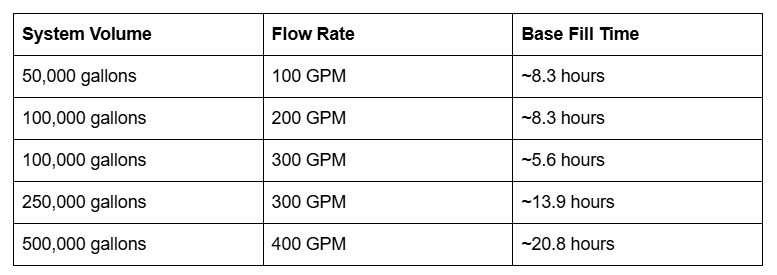
These are base calculations the minimum time assuming continuous, uninterrupted fill at the stated rate. They are useful for rough planning and for communicating the scale of the operation, but they should not be used as the schedule commitment without accounting for the factors below.
Why Actual Fill Time Is Almost Always Longer
1. Ramp-Up and Stabilization
An on-site RO system does not immediately produce permeate at full rated flow when it starts. The pretreatment train needs to stabilize, the membranes need to be flushed and brought to operating pressure, and the water quality needs to be verified before the permeate is directed into the fill header. A controlled ramp-up period of 30 minutes to several hours is standard practice.
Similarly, at the end of a fill, flow is typically ramped down rather than stopped abruptly to avoid hydraulic shock in the piping system.
These ramp periods are not in the simplified calculation.
2. Water Quality Holds
Before permeate enters the system, the commissioning team or QA representative needs to confirm that the water quality meets specification. This typically means collecting a sample, measuring conductivity and TDS, and comparing to the target parameters. If the initial permeate does not meet spec which can happen during startup if pretreatment is still stabilizing production is held until quality is confirmed.
During a fill, periodic water quality checks may also be required, particularly at transition points between flushing cycles and initial fills. Each hold period adds to the elapsed time.
3. Air Evacuation and Venting
As water enters a large piping system, air needs to be displaced and vented out. If automatic air vents are present and functioning, this happens progressively as the water level rises. In systems where air venting is manual or where automatic vents have not been commissioned, trapped air pockets slow the fill, cause flow irregularities, and may require the fill to pause while the system is walked down and manually vented.
This is one of the most variable factors in actual fill time and one of the most commonly underestimated.
4. Flushing Cycles
An initial fill for a new system is rarely a single fill-to-capacity operation. Most commissioning specifications include a flushing sequence filling the system, circulating to suspend and transport construction debris and loose scale, draining or partially draining, and repeating before the final fill with conditioned water takes place.
A system that requires two flush-and-drain cycles before the final fill is consuming two to three times the base fill volume of water and proportionally more calendar time. The flushing sequence also generates disposal volume that needs to be managed.
Understanding whether the commissioning specification requires flushing cycles and how many is essential to planning water supply volume and timeline realistically.
5. Pressure and Hose Routing Losses
The effective flow rate that reaches the fill connection is not the same as the rated output of the RO system. Pressure losses through delivery hoses, elevation changes, and the fill connection fitting reduce effective flow. On a site where the RO system is located 500 feet from the fill header connection and the delivery is at elevation, these losses are meaningful.
A system rated at 300 GPM at the permeate outlet may deliver 240-260 GPM at the fill connection after accounting for hose friction and elevation. This should be measured and verified during the startup phase, not assumed to match the nameplate.
6. Sampling and Documentation Holds
Many commissioning specifications require water quality samples to be collected at defined points during the fill — at startup, at intervals during production, and at completion — and held for a specified period or submitted for lab analysis before the next phase begins. If the specification requires a 24-hour lab hold on the initial fill sample before flushing begins, that 24 hours is in the schedule whether or not it appears in the base fill time calculation.
How to Build a Realistic Fill Schedule
Given the factors above, here is a practical approach to building a fill timeline that holds up in the field.
Step 1: Confirm the actual system volume from as-built data Use mechanical equipment schedules and piping isometrics, not early design estimates. Add 10-15% buffer for uncertainty in complex systems.
Step 2: Understand the commissioning specification requirements Read the commissioning specification before scheduling the water supply. Specifically look for: fill water quality targets, flushing sequence requirements, sampling and hold requirements, and documentation sign-off requirements. Each of these adds time.
Step 3: Get a confirmed sustained flow rate from your water provider The relevant number is not the nameplate output of the RO system. It is the confirmed sustained flow rate at the fill connection point on your site, after hose routing, elevation changes, and stabilization. Ask your provider for this number with the specific tie-in conditions for your site.
Step 4: Calculate base fill time for each fill and flush cycle If the spec requires two flush cycles and a final fill, calculate each separately. Total base time = (flush volume 1 ÷ flow rate) + (flush volume 2 ÷ flow rate) + (final fill volume ÷ flow rate), all converted to hours.
Step 5: Add operational time Add ramp-up time, quality verification holds, sampling holds, venting time, and any documentation sign-offs required between phases. A conservative estimate for these factors on a multi-cycle fill is 20-35% of the base calculated fill time.
Step 6: Confirm the discharge route for each cycle Each flush cycle produces a discharge volume. Confirm that the concentrate and flush discharge routes are sized for the cumulative volume, not just the initial fill.
Example: A 250,000-Gallon Fill with Two Flush Cycles
A data center cooling system with 250,000 gallons of total volume, commissioning specification requiring two flush cycles at 50% fill before final fill, with a 300 GPM sustained delivery rate:
Flush 1: 125,000 gallons at 300 GPM = ~7 hours base time
Drain and refill hold: 2 hours (venting, valve operation, QA check)
Flush 2: 125,000 gallons at 300 GPM = ~7 hours base time
Drain and refill hold: 2 hours
Final fill: 250,000 gallons at 300 GPM = ~14 hours base time
Ramp-up, stabilization, sampling holds: ~5 hours
Total realistic elapsed time: approximately 37 hours of active water production over a 2-3 calendar day window
The base calculation for just the final fill would have suggested 14 hours. The realistic schedule is more than double that. Neither number is wrong one is the minimum theoretical time for one fill operation, the other is what the full commissioning specification actually requires.
Planning for the Critical Path
The fill is on the critical path of every data center commissioning schedule. Equipment commissioning, safety system testing, and owner acceptance testing all follow it. A fill that slips by two days is a commissioning schedule that slips by two days, with all the downstream cost and milestone implications that creates.
The most effective risk mitigation is straightforward: plan the fill schedule realistically, secure the water supply and discharge route before the window opens, and choose a water supply system sized for the actual flow rate requirement not the minimum that could theoretically work if everything goes right.
Water Runner's Rapid Fill RO System is built around this reality 300-400 GPM sustained on-site production, municipal or trucked feed flexibility, and daily reporting to keep the commissioning team and GC informed throughout the fill. Launching Summer 2026.
FAQ
How do I find the total system volume for a data center cooling system? The most reliable source is the mechanical engineer's piping and instrumentation diagrams (P&IDs) combined with equipment schedules that list the fluid volume of each piece of equipment. Piping volume can be calculated from pipe diameter and total run length using standard pipe volume tables. If as-built data is not available, the mechanical contractor who installed the piping is typically the best source for an estimated volume.
What flow rate do I need to complete a fill within my commissioning window? Work backward from your required completion date. Determine the total water production volume needed across all fill and flush cycles, subtract the time allocated for holds and drain periods, and divide by the remaining available hours to get the minimum required flow rate. If the flow rate required exceeds what a single system can provide, a dual-system deployment or a larger primary system may be warranted.
Can multiple fill connections be used simultaneously to increase effective fill rate? Yes, in systems designed to accept it. Filling through multiple connection points simultaneously for example, filling chilled water and condenser water circuits concurrently effectively applies the available flow rate to multiple systems at once, compressing the total elapsed calendar time even if the total water volume remains the same. Coordinate with the commissioning agent to confirm that simultaneous fills are acceptable under the commissioning specification.
What is a controlled ramp-fill and why is it used? A controlled ramp-fill brings the system up to operating pressure gradually rather than opening the fill valve at full flow. This prevents hydraulic shock in new piping systems, allows air to be evacuated progressively rather than trapped, and gives the commissioning team time to observe system behavior before the full fill rate is applied. Most commissioning specifications for large cooling systems require a controlled ramp rather than a rapid fill.
Water Runner LLC is a TCEQ-licensed bulk water and industrial water solutions provider based in Midland, TX, serving data center construction and commissioning projects across Texas, New Mexico, and nationwide.